

Compressor vibration test and limit check
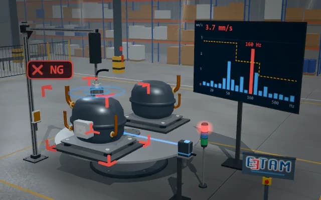
An accelerometer is brought into contact with the shell of the running compressor and the vibration signal is split into frequency bands. Each band is compared with the limit curve; any band above it is reported with its frequency.
Band amplitudes, the RMS value and the peak frequency are stored with the compressor serial number; a compressor above the limit is flagged on the stack light and removed from the table.
- 01 Index
- 02 Sensor contact
- 03 Spectrum
- 04 Decide
The dial table brings the next compressor to the test position and the photo-sensor confirms it.
- Vibration (RMS)
- —
- Peak frequency
- —
Scenes are illustrative simulations; they are not customer references or performance guarantees.
Need
The compressor shell is welded shut; bearing and piston faults show only in the vibration signature. The amplitude is small, and vibration from the carrier table, the neighbouring compressor and the line mixes into the measurement; the probe must touch every shell with the same force.
Solution approach
The dial table indexes the compressor to the test position; a presence photo-sensor confirms it and the unit is started. The accelerometer probe lowers from its slide onto the shell under constant preload, so contact force is the same on every unit. The signal is split into frequency bands, each compared with a frequency-dependent limit curve; a band above it is reported with the peak frequency.
Process steps
- 01
Index
The dial table brings the next compressor to the test position and the photo-sensor confirms it.
- 02
Sensor contact
The compressor runs and the accelerometer probe lowers onto the shell.
- 03
Spectrum
Vibration velocity is measured and averaged in frequency bands.
- 04
Decide
Band amplitudes are compared with the limit curve.
Related applications


Let us assess your application together
We test your sample in our laboratory and report on resolution, optics and lighting selection.