

Scab and pit depth measurement on steel plate
The plate passes beneath an overhead laser profiler on a roller line. Scab height and pit depth are measured in topography separated from the nominal surface; an out-of-limit region is linked to a regrinding decision.
Scab height, pit depth and defect coordinates are added to the plate record; the NG area is shown to the operator for regrinding.
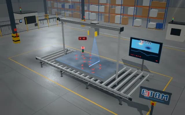
- 01 Plate
- 02 Laser
- 03 Map
- 04 Reference
- 05 Grinding
The plate enters the measurement region on rollers.
- Pit depth
- —
- Scab height
- —
- Defect area
- —
Scenes are illustrative simulations; they are not customer references or performance guarantees.
Need
Plate tilt and motion on rollers can be confused with defect height. A local sound surface is used as the reference to distinguish a scab from a pit.
Solution approach
A laser line crosses the plate and sections accumulate into a topography map during travel. A nominal plane is fitted to the sound area around each defect. Scabs above and pits below this plane are measured separately and their areas mapped to position.
Process steps
- 01
Plate
The plate enters the measurement region on rollers.
- 02
Laser
The transverse laser section samples the surface.
- 03
Map
Sections accumulate in a topography map.
- 04
Reference
A nominal plane is derived from the sound surface.
- 05
Grinding
Scab and pit limits feed the quality decision.
Related applications


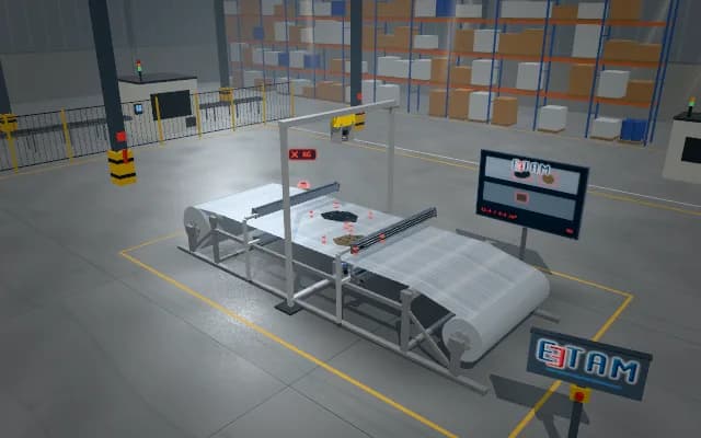


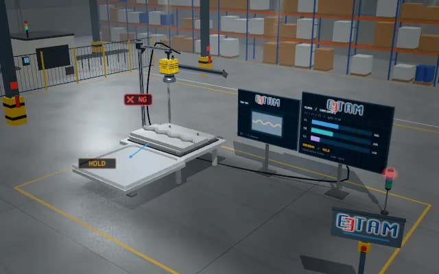
Let us assess your application together
We test your sample in our laboratory and report on resolution, optics and lighting selection.