

Surface and basis-weight uniformity inspection of nonwovens
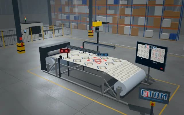
A wide nonwoven web passes line-scan cameras with backlight and top-light channels. Holes, fibre clumps and brightness variations are added to the web map; the defective metre is marked at the winder.
Defect type and metre position are recorded on the web map. The winder marker labels the corresponding metre; the transmission profile is sent to the operator display.

- 01 Web infeed
- 02 Two light channels
- 03 Scan
- 04 Uniformity
- 05 Metre mark
The web moves from unwinder to winder.
- Optical uniformity indicator
- —
- Web position
- —
Scenes are illustrative simulations; they are not customer references or performance guarantees.
Need
Fibre distribution and web vibration change transmission. Thin regions and holes, or dense fibre clumps and stains, must be separated in different light channels.
Solution approach
Line-scan cameras across the width collect transmission profiles with backlight below and surface stains with top light. An encoder links images to metre positions. The optical indicator for basis-weight uniformity is correlated with sample basis weights.
Process steps
- 01
Web infeed
The web moves from unwinder to winder.
- 02
Two light channels
Backlight and top light illuminate the web.
- 03
Scan
Cameras acquire the full width line by line.
- 04
Uniformity
Transmission profile and surface regions are compared.
- 05
Metre mark
The defective position is reported to the winder.
Related applications





Let us assess your application together
We test your sample in our laboratory and report on resolution, optics and lighting selection.