

Edge profile and coating width measurement on electrode coating
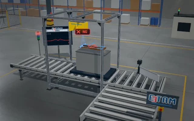
The electrode web leaving the coating head is scanned from above by a laser profile sensor. Edge height and coating boundaries are compared with a reference; the buildup region is marked and correction information is sent to the line controller.
Edge height and coating width are sent to the PLC for every cross-section; the buildup position is shown on the operator display and fed back to the coating head as correction information.

- 01 Web flow
- 02 Scan
- 03 Measure
- 04 Decide
The electrode web leaves the coating head and runs through the inspection span at constant speed.
- Edge elevation
- —
- Coating width
- —
Scenes are illustrative simulations; they are not customer references or performance guarantees.
Need
Dark coating and shiny foil reflect very differently; the coating edge can wander across the web, and foil vibration makes it difficult to separate actual edge buildup from movement of the reference plane.
Solution approach
A laser profile sensor looking down projects a line across the web; because height is measured directly, the brightness difference between coating and foil does not affect the result. The uncoated foil strip is the reference plane: the edge curve is extracted relative to it, and the width between the two coating boundaries is evaluated together with the local elevation at the edge.
Process steps
- 01
Web flow
The electrode web leaves the coating head and runs through the inspection span at constant speed.
- 02
Scan
The laser line scans the foil strip and the coating edge in the same cross-section.
- 03
Measure
Edge elevation and coating width are measured relative to the foil plane.
- 04
Decide
The buildup region is marked; correction information goes to the PLC.
Related applications




Let us assess your application together
We test your sample in our laboratory and report on resolution, optics and lighting selection.