

Alignment check of wound and stacked electrode layers
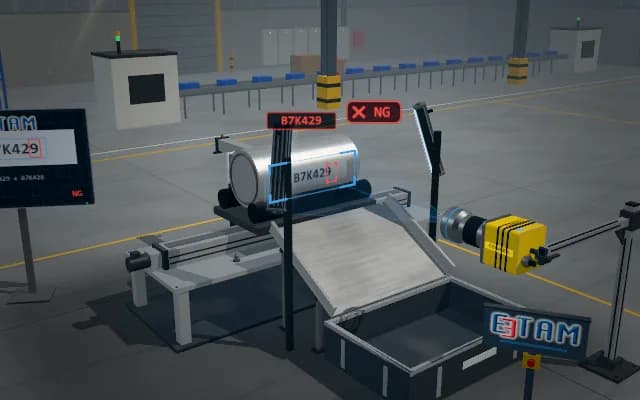
The wound electrode arrives on a roller carrier and is rotated about its axis; layer boundaries on the end face are extracted from the side with a profile sensor and a camera. Axially displaced layers are marked and the winding is pushed into the reject channel.
Layer displacement measurements are sent to the PLC and the operator display; a non-conforming winding is pushed onto the chute and from there into the reject bin.

- 01 Positioning
- 02 Acquire
- 03 Analyse
- 04 Decide
The winding arrives at the inspection position on its roller carrier.
- Layer displacement
- —
- End-plane range
- —
Scenes are illustrative simulations; they are not customer references or performance guarantees.
Need
Thin electrode and separator layer ends lie very close together. Reflections and winding-axis tilt make actual layer displacement difficult to distinguish from end-face inclination.
Solution approach
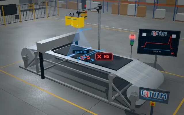
The carrier rollers rotate the winding about its axis; a side profile sensor tracks layer heights on the end face while an area camera tracks layer boundaries. Steps extending beyond the reference end plane are evaluated as layer displacement.
Process steps
- 01
Positioning
The winding arrives at the inspection position on its roller carrier.
- 02
Acquire
The sensor and camera scan the end face while the winding rotates about its axis.
- 03
Analyse
Layer ends are compared with the reference end plane.
- 04
Decide
Displaced layers are marked; the winding is pushed into the reject channel.
Related applications



Let us assess your application together
We test your sample in our laboratory and report on resolution, optics and lighting selection.