

Tuner decibel / noise detection
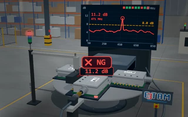
In the test nest the tuner module is contacted by an RF probe and pin contacts. While the frequency band is swept, the noise level is measured in dB and compared with the limit line; a peak above the limit is logged with its frequency and the module is rejected at the next station.
Peak noise, its frequency and the limit margin are written to the module serial record; a module above the limit is flagged by the nest LED and the stack light, and the line PLC separates it at the next station.
- 01 Contact
- 02 Sweep
- 03 Decide
- 04 Index
The pin block comes down, the RF probe mates with the connector and the module is powered.
- Peak noise
- —
- Peak frequency
- —
- Limit margin
- —
Scenes are illustrative simulations; they are not customer references or performance guarantees.
Need
The noise peak is narrow-band and low in level; a poor contact or a loose RF connection adds its own noise and makes a good module look faulty. The test time must fit within the line cycle.
Solution approach
In the nest on the rotary table the module is contacted by the pin block and the RF probe; once contact is confirmed the band is swept step by step and the noise level is checked against the limit line. The running peak and its frequency are tracked on the chart and above the module; the verdict goes to the nest LED and the stack light, and a module over the limit is separated at the next station.
Process steps
- 01
Contact
The pin block comes down, the RF probe mates with the connector and the module is powered.
- 02
Sweep
Across the band the noise level is measured step by step and plotted.
- 03
Decide
The highest level is compared with the limit value.
- 04
Index
The probes retract; the dial brings the next module into the station, and the result is carried on the nest LED at the side station.
Related applications




Let us assess your application together
We test your sample in our laboratory and report on resolution, optics and lighting selection.