

Bore diameter and wear check of wire-drawing dies
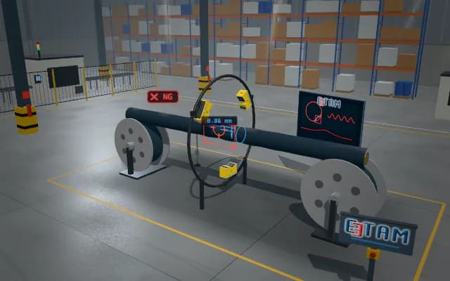
A wire-drawing die reaches the telecentric camera on an indexed table; a backlight underneath forms the bore silhouette. Bore contour gives the inner diameter and shape deviation caused by wear; a non-conforming die is moved to the rejection pocket.
Bore diameter and contour deviation are transferred to the die inspection record; an out-of-range die is moved to the rejection pocket and its bore image is presented to the operator.

- 01 Indexing
- 02 Backlight
- 03 Bore contour
- 04 Diameter and wear
- 05 Reject
The die is seated in the open-centre nest.
- Bore diameter
- —
- Contour deviation
- —
Scenes are illustrative simulations; they are not customer references or performance guarantees.
Need
A reflective die entrance produces reflections under front lighting, and the conical inlet can hide the actual throat diameter. Dirt and wear can create similar appearances at the bore edge.
Solution approach
An overhead telecentric camera views the narrowest bore section as a silhouette against the backlight below. A circular reference is fitted to the calibrated contour; inner diameter and local contour deviation are measured. Die placement and throat visibility are verified with samples.
Process steps
- 01
Indexing
The die is seated in the open-centre nest.
- 02
Backlight
Light passes through the bore from below to the camera.
- 03
Bore contour
The edge of the narrowest section is separated.
- 04
Diameter and wear
Diameter and deviation are measured against the circular reference.
- 05
Reject
The worn die is pushed into the rejection pocket.
Related applications




Let us assess your application together
We test your sample in our laboratory and report on resolution, optics and lighting selection.