

Laser-mark accuracy test on drinking glasses (bubble method)
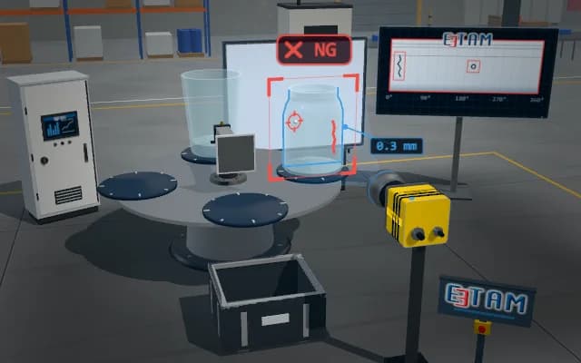
The nucleation point laser-etched on the inner base is tested by filling the glass with a carbonated test liquid. In a backlit side view the axis of the bubble column is located and its offset from the glass axis is measured. A glass outside tolerance is lifted off the pallet by a gantry gripper.
Offset and bubble count are written to the traceability record for every glass; a glass outside tolerance is moved to the reject container by the gantry robot and the pallet continues with an empty nest. The result is shown on the stack light and the operator display.

- 01 Fill
- 02 Bubbles
- 03 Acquire
- 04 Measure
- 05 Decide
The pallet sensor detects the glasses and the nozzles fill them with carbonated test liquid.
- Axis offset
- —
- Bubble count
- —
Scenes are illustrative simulations; they are not customer references or performance guarantees.
Need
The laser mark is a frosted sub-millimetre spot inside the glass and hard to image directly. The bubble column sways in the liquid and the conical glass wall refracts the view; the column axis can only be located reliably from many bubbles at once.
Solution approach
A pallet-presence sensor starts the fill; once the glasses are full they are imaged side-on in one frame against a backlight, and the bubbles separate as dark blobs on the bright background. The symmetry axis is derived from the glass edges and the column axis from the bubble blobs; the offset between the two axes and the bubble count give the verdict.
Process steps
- 01
Fill
The pallet sensor detects the glasses and the nozzles fill them with carbonated test liquid.
- 02
Bubbles
The laser mark acts as a nucleation site; a bubble column rises to the surface.
- 03
Acquire
The backlight strobes and both glasses are captured side-on in one frame.
- 04
Measure
The bubble-column axis is located and its offset from the glass axis is measured.
- 05
Decide
Offset and bubble count are compared with the limits; a glass outside tolerance is moved to the reject container by the gripper.
Related applications



Let us assess your application together
We test your sample in our laboratory and report on resolution, optics and lighting selection.