

Crack and form inspection of cold-forged heads
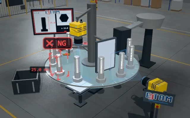
Upright bolts on an indexing dial arrive under a dome light. The top image checks cracks and corner fill, while the side silhouette checks head height and eccentricity; a non-conforming part is separated by an air jet.
The crack mark, head height and eccentricity are written to the part record. The PLC triggers the nozzle at the dial outlet to separate a non-conforming bolt into the reject crate.

- 01 Indexing
- 02 Top view
- 03 Side view
- 04 Shape decision
- 05 Reject
The bolt nest reaches the inspection axis.
- Crack length
- —
- Head height
- —
- Eccentricity
- —
Scenes are illustrative simulations; they are not customer references or performance guarantees.
Need
Reflections on a bright forged surface hide fine cracks. An underfilled corner and eccentricity must be evaluated separately from errors in the part position.
Solution approach
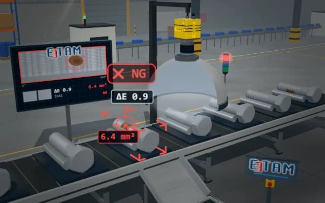
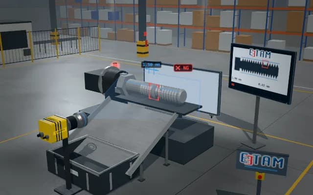
The overhead dome reduces directional glare; an area camera locates the head contour and dark crack traces. A side camera with a backlight measures head height and eccentricity relative to the shank from the silhouette.
Process steps
- 01
Indexing
The bolt nest reaches the inspection axis.
- 02
Top view
The head contour and crack are imaged under the dome light.
- 03
Side view
Height and eccentricity are measured from the backlit silhouette.
- 04
Shape decision
Contour and crack traces are compared with acceptance criteria.
- 05
Reject
A bolt with a crack is separated into the crate by the air nozzle.
Related applications


Let us assess your application together
We test your sample in our laboratory and report on resolution, optics and lighting selection.