

Colour-to-colour register control in printing
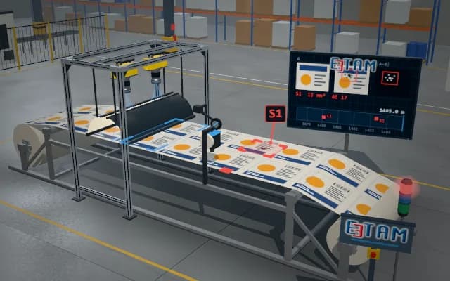
A printed sheet passes under a colour line-scan camera with homogeneous lighting from above. At the register marks in the corners the position of every colour layer is measured against the reference layer; an out-of-tolerance offset is sent to the printing unit as a correction and the sheet is flagged in the pile.
Offset values per layer are passed to the register setting of the printing unit as a correction; an out-of-tolerance sheet is identified in the pile by a marker tab, and the values are followed on the operator display and in the job record.

- 01 Infeed
- 02 Scan
- 03 Measure
- 04 Decide
The sheet leaves the printing units and approaches the camera on the conveyor.
- Machine-direction offset
- —
- Cross-direction offset
- —
- Layer
- —
Scenes are illustrative simulations; they are not customer references or performance guarantees.
Need
Colour layers are printed in separate units; paper stretching with moisture and small shifts in unit setting move the layers apart. The offset is as fine as a hair, is not the same everywhere on the print and cannot be followed by eye at line speed.
Solution approach
A colour line-scan camera sees the sheet across its width in one line; symmetric bar lights from both sides light the surface evenly and without glare. The image is aligned to the reference layer; at the register marks and at selected print edges the edge of each colour is found in its own colour channel and the difference to the reference is measured in two axes.
Process steps
- 01
Infeed
The sheet leaves the printing units and approaches the camera on the conveyor.
- 02
Scan
The sheet passes under the line-scan camera; the colour image builds up line by line.
- 03
Measure
The image is aligned to the reference; at the marks the offset of every layer is measured in two axes.
- 04
Decide
The offset is compared with the tolerance; if outside, a correction is sent to the printing unit.
Related applications




Let us assess your application together
We test your sample in our laboratory and report on resolution, optics and lighting selection.