

Hole and tear mapping on paper webs
The paper web runs under tension between a light line below and a line-scan camera above. Holes and edge tears show up as bright regions in transmitted light; their size is measured and the encoder supplies the metre and cross-web position.
Every opening is written to the roll map with class, size, metre and cross-web position; the map is attached to the winding record and used to stop the rewinder at the defective metre.

- 01 Scan
- 02 Detect
- 03 Locate
- 04 Log
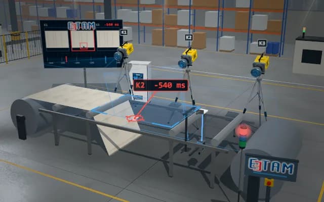
The web runs over the light line; the transmitted-light image builds up line by line.
- Position
- —
- Cross-web position
- —
- Size
- —
Scenes are illustrative simulations; they are not customer references or performance guarantees.
Need
While the web runs fast, a small hole disappears in a top view among the paper texture and formation cloudiness. An edge tear is confused with the lateral wander of the web, and the place of the defect on the roll cannot be found afterwards.
Solution approach
The light source sits below the web and the line-scan camera directly opposite: paper attenuates the light while an opening passes it directly, giving a bright region of high contrast. The web edge is tracked in every line, so an edge tear is separated from wander. Line triggering comes from the encoder, so length, width and position of every region are measured on one scale.
Process steps
- 01
Scan
The web runs over the light line; the transmitted-light image builds up line by line.
- 02
Detect
A bright region is found and separated as a hole or an edge tear.
- 03
Locate
The size of the region is measured; metre and cross-web position come from the encoder counter.
- 04
Log
The defect is entered in the roll map and added to the winding record.
Related applications





Let us assess your application together
We test your sample in our laboratory and report on resolution, optics and lighting selection.