

Machine performance analysis with a high-speed camera
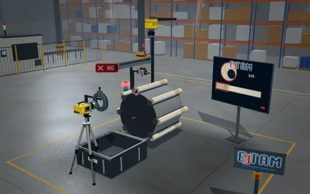
A fast-running mechanism is recorded at a high frame rate. In the slow-motion footage the moving parts are tracked frame by frame; pusher and drum motion are compared in a timing diagram and a late motion is measured in milliseconds.
The measured delay and cycle time are written to the maintenance report; the stack light flags the late cycle, the recording segment is kept as evidence and the mechanism is adjusted accordingly.

- 01 Record
- 02 Slow motion
- 03 Track
- 04 Decide
The mechanism is recorded at a high frame rate while it runs at production speed; the exit photo-sensor provides the recording trigger.
- Frame rate
- —
- Cycle time
- —
- Delay
- —
Scenes are illustrative simulations; they are not customer references or performance guarantees.
Need
The mechanism runs tens of cycles per second; an overlap of a few milliseconds between pusher and drum cannot be seen by eye or with a standard camera, only its result as crushed product and stoppages. Because the fault is intermittent, the right instant has to be captured.
Solution approach
A high-speed camera on a tripod views the mechanism from the side; continuous spotlights give enough light for short exposures. The recording is held in a ring buffer and stopped by the fault signal of the exit photo-sensor; in slow motion the pusher and the drum pocket are tracked frame by frame, the timing diagram of both motions is drawn and the delay is converted from frames to milliseconds.
Process steps
- 01
Record
The mechanism is recorded at a high frame rate while it runs at production speed; the exit photo-sensor provides the recording trigger.
- 02
Slow motion
The recording is slowed down; motion too fast for the eye becomes visible.
- 03
Track
Pusher and drum pocket are tracked frame by frame and the timing diagram is drawn.
- 04
Decide
The pusher return is compared with the instant the drum starts to index; a late cycle is flagged on the stack light.
Related applications




Let us assess your application together
We test your sample in our laboratory and report on resolution, optics and lighting selection.