

Locating compressor gas-brazing points and guiding the robot
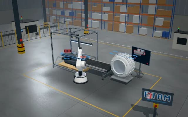
The compressor is scanned by two 3D sensors; the tube-to-shell joints are located in the point cloud and sent to the robot together with their deviation from the taught position. A joint that is not found is rescanned; the robot takes the torch to each point using the corrected coordinates.
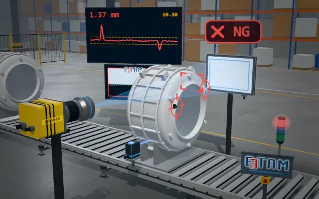
Corrected coordinates and deviation of the three joints go to the robot controller and are listed on the display; if a joint is not found the robot is not started and the part is rescanned or set aside.

- 01 3D scan
- 02 Locate
- 03 Guidance
- 04 Result
The compressor arrives and the laser lines of two sensors sweep the shell and the tubes.
- Points found
- —
- Active target
- —
- Position offset
- —
Scenes are illustrative simulations; they are not customer references or performance guarantees.
Need
The compressor shell is shiny and curved, the tubes are thin and sit a few millimetres differently on every part; on a fixed taught path the torch misses the joint. A tube behind the shell can stay in the shadow of a single sensor.
Solution approach
Two 3D laser profile sensors scan the shell from both sides; the two views are merged into one point cloud, shrinking the region shadowed by the shell. The joints where tube meets shell are located in the cloud, their deviation from the taught position is computed and the corrected targets are sent to the robot. A joint not found is rescanned; if it is still missing the robot is not started.
Process steps
- 01
3D scan
The compressor arrives and the laser lines of two sensors sweep the shell and the tubes.
- 02
Locate
Tube-to-shell joints are found in the cloud; a joint not found is rescanned.
- 03
Guidance
The robot takes the torch to each point in turn using the corrected coordinates.
- 04
Result
All points have been processed; the compressor leaves the station.
Related applications




Let us assess your application together
We test your sample in our laboratory and report on resolution, optics and lighting selection.