

Vision-guided precision robotic assembly of TV panels
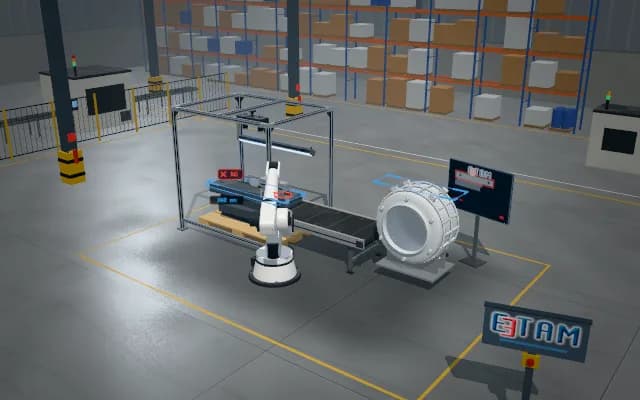
While the robot holds the display cell above the chassis, two cameras image diagonally opposite corners. X, Y and angular offsets are computed from the corner positions; if the first measurement is out of tolerance the robot corrects until the offsets are within tolerance, then lowers the cell into its seat.
The X, Y and angle deviations are passed to the robot controller as an offset; the post-release verification value is written to the unit record, and a unit out of tolerance is flagged for re-alignment.

- 01 Pre-position
- 02 Acquire
- 03 Correct
- 04 Set down
- 05 Verify
The chassis stops in the station and the robot brings the cell above it.
- X offset
- —
- Y offset
- —
- Angle offset
- —
Scenes are illustrative simulations; they are not customer references or performance guarantees.
Need
The clearance between the cell and its seat in the chassis is tight; robot repeatability alone is not enough, and the cell sits slightly differently in the gripper at every pick. The glass edge has low contrast; unless both corners are seen at the same time an angular error goes unnoticed.
Solution approach
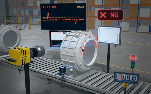
Two long-focal-length cameras with ring lights look squarely at diagonal corners and see cell and chassis corner in the same frame; X, Y and angle offsets are computed from the two corners. If the first measurement is out of tolerance the offset is sent to the robot and the measurement is repeated; once within tolerance the cell is lowered and the corners are verified once more after release.
Process steps
- 01
Pre-position
The chassis stops in the station and the robot brings the cell above it.
- 02
Acquire
Two cameras image diagonally opposite corners of cell and chassis at the same time; the first offset is out of tolerance.
- 03
Correct
The computed X, Y and angle offsets are sent to the robot and the measurement is repeated.
- 04
Set down
Once the offsets are within tolerance the cell is lowered into the seat.
- 05
Verify
After release the corners are measured once more.
Related applications




Let us assess your application together
We test your sample in our laboratory and report on resolution, optics and lighting selection.