

Solder joint inspection on boards
Solder joints are imaged twice, lit from above and from a low angle. Fillet shape, height and pad coverage are derived from how the reflection is distributed; insufficient solder and bridges between joints are marked separately.
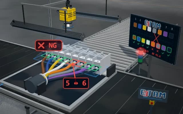
Each solder joint is marked with its result colour; fillet and coverage summaries and the bridge finding remain on the operator display, while the overall pallet decision appears on the signal tower.

- 01 Infeed
- 02 Top light
- 03 Angled light
- 04 Fillet analysis
- 05 Decide
The pallet indexes into the station with the solder side up.
- Lowest fillet
- —
- Pad coverage
- —
- Bridges
- —
Scenes are illustrative simulations; they are not customer references or performance guarantees.
Need
Shiny solder changes appearance with illumination angle. Pin shadows and reflections from neighbouring fillets can conceal the exposed pad of an insufficient joint or a bridge between joints.
Solution approach
The top ring light highlights flat pads while low-angle bar lights highlight sloped fillet surfaces. Contours from both exposures are compared in corresponding joint regions; the illustrative fillet profile, pad coverage and connections between neighbouring regions are evaluated together.
Process steps
- 01
Infeed
The pallet indexes into the station with the solder side up.
- 02
Top light
The ring light strobes: flat pads and pin tips appear bright, sloped solder dark.
- 03
Angled light
The side bar lights strobe: the fillet slope shows up as a bright ring.
- 04
Fillet analysis
Contour, height and pad coverage are evaluated joint by joint.
- 05
Decide
Measurements are compared with lower limits; neighbouring joints are checked for bridges.
Related applications






Let us assess your application together
We test your sample in our laboratory and report on resolution, optics and lighting selection.