

Connector pin parallelism and defect inspection
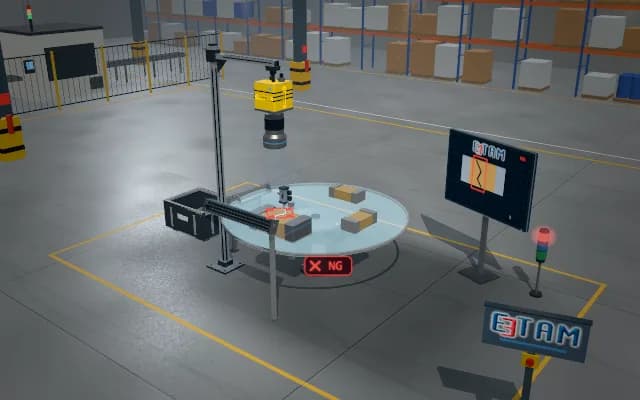
The connector arrives at the station on a dial table. A side camera measures tip height and lean from the pin silhouette against a backlight, and a top camera measures the tip positions; a pin beyond the coplanarity or parallelism limit is marked.
Coplanarity, axis lean and tip deviation are combined in the connector record; the faulty pin is marked in both views and the overall decision is sent to the display and signal tower.

- 01 Index
- 02 Side view
- 03 Top view
- 04 Measure
- 05 Decide
The table turns 90° and the next connector stops at the measuring station.
- Coplanarity
- —
- Axis lean
- —
- Tip deviation
- —
Scenes are illustrative simulations; they are not customer references or performance guarantees.
Need
Two pin rows can overlap in a side view, and reflections from gold-coloured surfaces obscure the true tip boundary. A single view cannot separate tip height from lateral deviation.
Solution approach
The side camera captures pin silhouettes against a backlight; axis lean and tip height are compared with a nominal band. The top camera images both rows separately under ring lighting; deviation between nominal tip squares and actual tip points is verified from this second view.
Process steps
- 01
Index
The table turns 90° and the next connector stops at the measuring station.
- 02
Side view
The backlight strobes and the side camera captures the silhouette of the pin row.
- 03
Top view
The ring light strobes and the top camera images the pin tips.
- 04
Measure
Pin axes and tip heights are extracted, then the deviation of the tips from nominal position.
- 05
Decide
Coplanarity, parallelism and tip position are compared with the limits.
Related applications





Let us assess your application together
We test your sample in our laboratory and report on resolution, optics and lighting selection.