

Visual inspection and functional testing of electronic boards
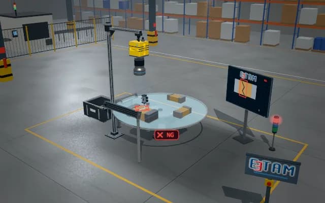
In the test nest the board is first imaged unpowered: are components and modules in place? Then the probe comes down and the board is powered; voltage and current are measured, and the camera verifies that LEDs and display segments light up.
Visual findings, electrical readings and verification of emitting regions are linked to one test record; the display image and decision go to the operator, and the overall result goes to the signal tower.

- 01 Load
- 02 Visual check
- 03 Power-up
- 04 Function
- 05 Decide
The shuttle brings the next board under the test head.
- Steps passed
- —
- Supply voltage
- —
- Current
- —
Scenes are illustrative simulations; they are not customer references or performance guarantees.
Need
A display segment that looks intact on an unpowered board may fail to light when powered. Ambient light and surface reflections can make an emitting LED look similar to a reflective housing.
Solution approach
The shuttle brings the board under a fixed top camera for an unpowered presence check with ring lighting. After probe contact, voltage and current are acquired; the ring light is dimmed for LED and segment testing and emitting regions are compared with the expected test mask.
Process steps
- 01
Load
The shuttle brings the next board under the test head.
- 02
Visual check
The ring light strobes and the board is scanned for presence of components and modules.
- 03
Power-up
The probe docks on the connector; supply voltage and current draw are measured.
- 04
Function
The ring light is dimmed; LEDs light in sequence and display segments light up, and the camera compares them with the test mask.
- 05
Decide
The results of the test steps are collected in one record.
Related applications





Let us assess your application together
We test your sample in our laboratory and report on resolution, optics and lighting selection.