

Tread depth and groove geometry measurement
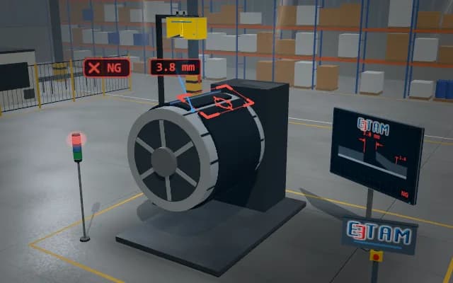
The tyre is held at a rotary station; an overhead profile sensor scans sections of the tread grooves. The groove floor is measured relative to the tread reference plane; depth and shape deviation are compared with the acceptance range.
Depth and section deviation are displayed to the operator; the classification PLC receives the separate-routing decision for a non-conforming tyre.

- 01 Hold
- 02 Rotate
- 03 Section
- 04 Reference
- 05 Decide
The tyre is held on the measuring axis.
- Groove depth
- —
- Section deviation
- —
Scenes are illustrative simulations; they are not customer references or performance guarantees.
Need
Black tread reflects little light and deep groove floors may be hidden from the viewing direction. Tyre rotation also changes the reference surface.
Solution approach
The overhead profile sensor laser line crosses the tread width. A local reference is built from tread peaks in the calibrated section; groove-floor depth and section shape are assessed relative to that reference.
Process steps
- 01
Hold
The tyre is held on the measuring axis.
- 02
Rotate
The tread passes through the overhead laser line.
- 03
Section
Tread peaks and groove floor are separated.
- 04
Reference
Groove depth is found relative to the local tread plane.
- 05
Decide
The tyre is diverted for shallow or misshaped grooves.
Related applications




Let us assess your application together
We test your sample in our laboratory and report on resolution, optics and lighting selection.