

Placing different components into oriented assembly-kit nests
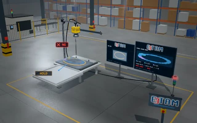
Each placement links to its destination kit nest. The sequence advances for a verified part and empty nest; wrong geometry, orientation or occupancy keeps the kit on controlled hold. Calibration, grip and PLC sequence are animated as an illustrative simulation.
Each placement links to its destination kit nest. The sequence advances for a verified part and empty nest; wrong geometry, orientation or occupancy keeps the kit on controlled hold.

- 01 Image and source
- 02 Pose and plan
- 03 Grip and lift
- 04 Transfer
- 05 Release and final check
Image the presented part and kit nests; establish geometry and occupancy context.
- Illustrative pose offset
- —
- Illustrative grip confirmation
- —
- Completed transfers
- —
Scenes are illustrative simulations; they are not customer references or performance guarantees.
Need
Assembly-kit flanges require the correct nest and orientation. An overlooked similar item or occupied nest can produce an incomplete kit, wrong sequence or placement conflict; identity and occupancy need joint tracking.
Solution approach
Locate part geometry and orientation on the presentation table and occupancy in the kit. Select the robot target from the kit-recipe association. Grip, lift and carry the flange into an empty oriented nest; compare final part-to-nest association and kit completeness with the record.
Process steps
- 01
Image and source
Image the presented part and kit nests; establish geometry and occupancy context.
- 02
Pose and plan
The kit recipe associates the part with an empty target nest and prepares an oriented approach.
- 03
Grip and lift
Grip and lift the flange from the presentation table; confirm part presence.
- 04
Transfer
Carry the flange above its correct kit nest; other nests retain their identities.
- 05
Release and final check
After lowering and release, check geometry and the kit-sequence record.
Related applications





Let us assess your application together
We test your sample in our laboratory and report on resolution, optics and lighting selection.