

Flash, tear, colour and moulding-defect analysis at the injection-moulding outfeed
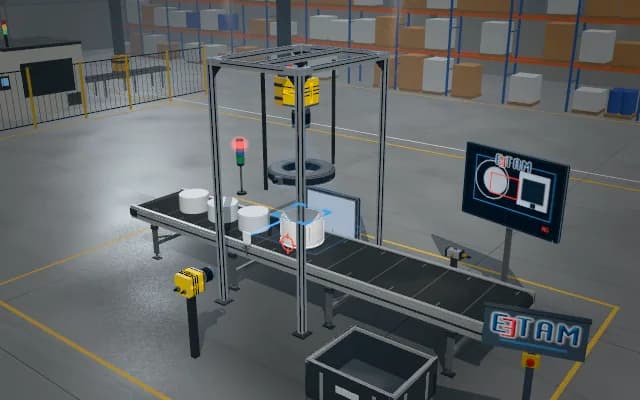
The part leaving the machine is imaged from above twice in succession under two opposing low-angle bar lights on the photo-sensor trigger. The measured contour is compared with the nominal one: excess material is marked as flash, a missing region as a tear or short shot; colour difference is measured as well.
Contour deviation, defect area and ΔE are recorded against the moulding cycle; a defective part is routed by the diverter flap into the chute and the regrind bin. Consecutive rejects go to the machine PLC as a cycle alarm.
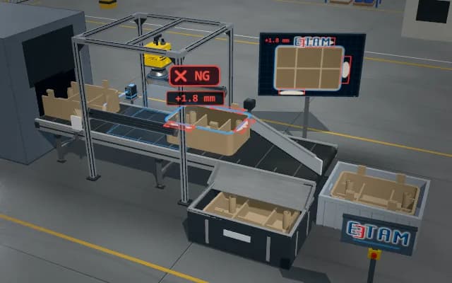
- 01 Infeed
- 02 Acquire
- 03 Contour check
- 04 Decide
The part leaves the injection machine and travels to the station on the belt; the photo-sensor sees it.
- Contour error
- —
- Defect area
- —
- Colour diff. ΔE
- —
Scenes are illustrative simulations; they are not customer references or performance guarantees.
Need
Flash has the same colour as the part, is often paper-thin and extends translucently beyond the edge; under direct light it does not separate from the body. A short shot removes only one corner and the part lands on the belt at a different angle every time.
Solution approach
Low-angle bar lights make edges and thin flash stand out as a bright line; both lights strobe in turn and images from opposite sides are merged, so no edge hides in its own shadow. Part position and angle come from the contour and the nominal contour is aligned onto it; area outside counts as flash, area missing inside as a short shot. In the same image body colour is compared with the reference.
Process steps
- 01
Infeed
The part leaves the injection machine and travels to the station on the belt; the photo-sensor sees it.
- 02
Acquire
The two bar lights strobe in turn and the top-view camera captures two images of the part.
- 03
Contour check
The outer contour of the part is extracted and overlaid on the nominal contour.
- 04
Decide
Contour deviation, defect area and colour difference are compared with their limits.
Related applications



Let us assess your application together
We test your sample in our laboratory and report on resolution, optics and lighting selection.