

Winding accuracy and alignment check on plastic film rolls
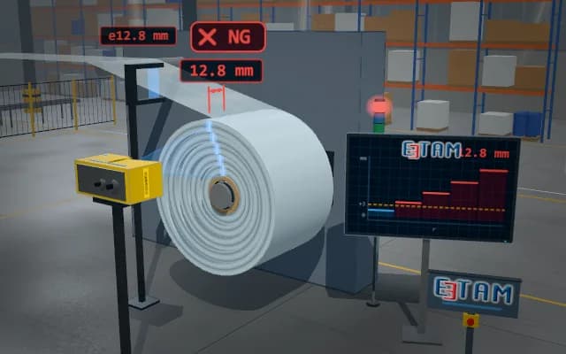
While winding, a laser profile sensor scans the end face of the roll along its radius; the axial offset of the layers is measured as a stepped profile. A fork-type edge sensor follows the edge of the incoming film. When the offset exceeds the tolerance, winding is stopped and the roll is changed.
The total offset and the largest step are sent to the winder drive; on a tolerance violation winding is stopped, the stack light warns and the roll record is flagged. The profile curve is shown on the operator display.
- 01 Winding
- 02 Laser profile
- 03 Edge profile
- 04 Drift watch
- 05 Decide
The film passes the idler roller and winds onto the roll on the cantilever shaft; the edge sensor follows the film edge.
- Total offset
- —
- Largest step
- —
- Roll diameter
- —
Scenes are illustrative simulations; they are not customer references or performance guarantees.
Need
On the end face of a clear film roll the layer boundaries are almost invisible; the roll rotates, vibrates and its diameter grows continuously. Edge wander starts as a few hundred microns per layer and becomes obvious only after the outer layers accumulate, when the roll is already scrap.
Solution approach
The profile sensor faces the end face; the laser line falls along the radius and reads the axial position of every layer group as a height, so roll rotation and diameter growth do not affect the result. The fork edge sensor follows the edge of the incoming film and shows the source of the drift early. A flat profile lets winding continue; when the step sum exceeds the tolerance the winder stops.
Process steps
- 01
Winding
The film passes the idler roller and winds onto the roll on the cantilever shaft; the edge sensor follows the film edge.
- 02
Laser profile
The laser line falls on the end face along the radius and the sensor reads the profile.
- 03
Edge profile
The axial position of each layer is extracted; a flat end face gives a flat profile.
- 04
Drift watch
As the film edge wanders, the outer layers shift forward and the profile becomes stepped.
- 05
Decide
The total offset is compared with the tolerance limit; on a violation winding stops and the roll is changed.
Related applications



Let us assess your application together
We test your sample in our laboratory and report on resolution, optics and lighting selection.