

Vision-guided robotic feeding from mixed panel stacks
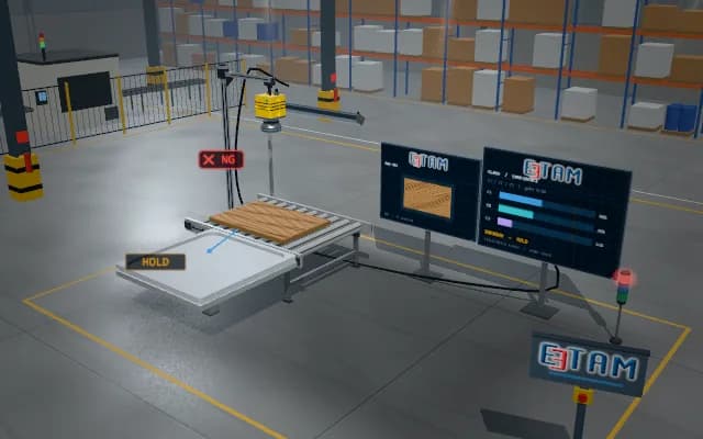
Panels of mixed size and position rest on a pallet; a laser profile scanner on the robot arm measures the top of the stack and produces a point cloud. The top layer is separated from the cloud, the pose and grasp point of the uppermost panel are computed; the vacuum gripper picks the selected panel and places it on the CNC infeed.
The pose and grasp point of the selected panel are sent to the robot controller; an overlapped or tilted candidate is skipped and the next panel is selected, and the code of the picked panel is passed to the CNC program.

- 01 Scan
- 02 Segment
- 03 Grasp pose
- 04 Pick
- 05 Place
The laser scanner on the robot arm sweeps over the stack; the point cloud is built.
- Panel angle
- —
- Top layer height
- —
- Panels left
- —
Scenes are illustrative simulations; they are not customer references or performance guarantees.
Need
The panels in the stack differ in size and are shifted and slightly rotated; the top layer and the panel below are the same colour, so edge separation in a 2D image is unreliable. On an overlapped panel the grasp point can land on a gap and the gripper may lift the neighbouring panel too.
Solution approach
The laser scanner on the robot arm sweeps over the stack at constant speed; profiles combined with the robot position give the point cloud. The top layer is segmented from height jumps and a rectangle is fitted to each panel; the exposed panel that does not overlap its neighbour is chosen. Its centre and angle are converted to robot coordinates, giving a grasp pose with all cups inside the panel.
Process steps
- 01
Scan
The laser scanner on the robot arm sweeps over the stack; the point cloud is built.
- 02
Segment
The top layer is separated from height jumps; a rectangle is fitted to each panel.
- 03
Grasp pose
An overlapped candidate is skipped; the centre and angle of the exposed panel are converted to robot coordinates.
- 04
Pick
The vacuum gripper descends to the panel at the computed pose and lifts it.
- 05
Place
The panel is placed on the CNC infeed conveyor; the robot returns for a new scan.
Related applications



Let us assess your application together
We test your sample in our laboratory and report on resolution, optics and lighting selection.