

Injector end-of-line quality check
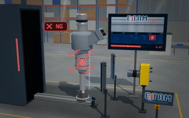
Injectors on a rotary indexing table pass three camera stations in turn: connector pins, nozzle-tip silhouette and O-ring presence are checked. A part that fails any check is pushed off the table into the reject chute.
Results from the three stations are shown on the operator display and stack light. An injector with no O-ring is pushed into the reject chute.

- 01 Index
- 02 Connector
- 03 Nozzle tip
- 04 O-ring
- 05 Decide
The table indexes one step; every nest moves on to the next station.
- Pin count
- —
- Tip protrusion
- —
- O-ring
- —
Scenes are illustrative simulations; they are not customer references or performance guarantees.
Need
The connector, nozzle tip and O-ring face different directions. Bright metal and dark elastomer do not provide enough contrast under the same light, so one image cannot cover every check.
Solution approach
The indexing table carries the part through three fixed views, each with lighting matched to its check. A ring-lit camera looking along the connector axis images the pins, a backlight between table and part silhouettes the nozzle tip, and a top-view camera images the O-ring. A photo-sensor confirms the part is seated in its nest; the three results are combined.
Process steps
- 01
Index
The table indexes one step; every nest moves on to the next station.
- 02
Connector
A camera with a ring light counts the connector pins and measures their position.
- 03
Nozzle tip
The nozzle tip is imaged against a backlight and its protrusion is measured.
- 04
O-ring
A top-view camera verifies that the O-ring on the fuel inlet is in place.
- 05
Decide
The three station results are combined; a non-conforming part is rejected.
Related applications



Let us assess your application together
We test your sample in our laboratory and report on resolution, optics and lighting selection.