

Spray-hole position and angle check on the injector nozzle
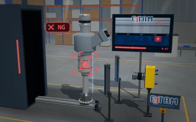
The nozzle tip is imaged from above by a telecentric camera; the position and angular spacing of the spray holes on the pitch circle are measured. A rotary nest brings each hole in turn onto the axis of an oblique camera, which looks along the hole to measure its axis inclination. A hole that deviates from nominal geometry is highlighted.
Hole position, angular-spacing deviation and the axis angle of every hole appear on the operator display. A hole outside tolerance is highlighted on the part; the combined verdict is sent to the stack light.

- 01 Position
- 02 Top acquisition
- 03 Hole spacing
- 04 Axis inclination
- 05 Decide
The slide brings the next nozzle under the top camera.
- Position deviation
- —
- Spacing deviation
- —
- Axis angle
- —
Scenes are illustrative simulations; they are not customer references or performance guarantees.
Need
Hole openings on the bright, curved nozzle tip appear elliptical, and reflections can hide their edges. A top view gives the position of a hole but not its direction: axis inclination only shows when looking along the hole, so every hole has to be brought onto a camera axis one at a time.
Solution approach
A telecentric top camera measures the hole centres under ring light without perspective error; position and angular spacing are checked against the pitch circle. An oblique camera sits on the nominal hole axis and a rotary nest indexes the nozzle. If hole mouth and hole bottom look concentric, the axis is correct; their offset gives the inclination. Cameras and nest axis share one calibration.
Process steps
- 01
Position
The slide brings the next nozzle under the top camera.
- 02
Top acquisition
The ring light strobes and the telecentric camera images the hole openings on the dome from above.
- 03
Hole spacing
Hole centres are located in the top view; their positions and angular spacing are compared with the nominal places on the pitch circle.
- 04
Axis inclination
The rotary nest brings each hole in turn onto the axis of the oblique camera; the axis angle is measured by looking along the hole.
- 05
Decide
Position, angular spacing and axis inclination are evaluated together; the deviating hole is highlighted.
Related applications




Let us assess your application together
We test your sample in our laboratory and report on resolution, optics and lighting selection.