

Engine cylinder surface analysis
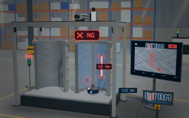
A rotating probe head travels down the bore and scans the honed surface under ring illumination; the images are unwrapped into a single angle-versus-depth picture. An AI model marks scratch and porosity regions in that picture.
The unwrapped image, defect position and length are linked to the cylinder record. The operator display shows the defect regions, and the stack light indicates the inspection result.
- 01 Positioning
- 02 Scan
- 03 Surface analysis
- 04 Decide
The probe head is aligned with the cylinder axis and enters the bore.
- Scan depth
- —
- Defect regions
- —
- Scratch length
- —
Scenes are illustrative simulations; they are not customer references or performance guarantees.
Need
The honed surface is already covered with fine cross-hatch lines, so a real scratch or pore shows little contrast against that texture. Reflections change with angle on the narrow curved bore wall, and a single fixed view cannot cover the full circumference and depth.
Solution approach
A side-view probe rotates as it descends along the bore axis; a ring light around the probe illuminates the nearby wall. Images mapped to angle and depth form an unwrapped view, where an AI model marks scratch and porosity regions that differ from the honing texture.
Process steps
- 01
Positioning
The probe head is aligned with the cylinder axis and enters the bore.
- 02
Scan
The head rotates as it descends; the whole wall is imaged under ring light.
- 03
Surface analysis
The AI model searches the unwrapped image for regions that deviate from the honing texture.
- 04
Decide
Detected regions are logged with position and size in the cylinder record.
Related applications






Let us assess your application together
We test your sample in our laboratory and report on resolution, optics and lighting selection.