

Heating element inspection and test system
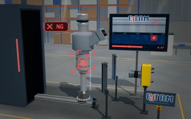
The tubular heater indexes into the test nest; contact probes close on the terminals and resistance is measured. Once powered, a thermal camera extracts the temperature profile along the tube and a section that does not heat sufficiently is marked on the profile.
Cold resistance, peak temperature and temperature spread along the tube are recorded; thermal image and profile are linked to the same part’s OK or NG result.

- 01 Index
- 02 Electrical
- 03 Heat-up
- 04 Thermal check
- 05 Decide
The table indexes one step and the next heater arrives in the test nest.
- Resistance
- —
- Peak temp.
- —
- Temp. spread
- —
Scenes are illustrative simulations; they are not customer references or performance guarantees.
Need
Even when heater resistance is within the acceptance range, one section of the tube may not heat sufficiently. Electrical testing and temperature distribution along the tube are checked together in one cycle.
Solution approach
The table indexes the heater; after detection, probes close on its terminals and cold resistance is measured. Once powered, the overhead thermal camera sees the tube path in one frame; temperature distribution is extracted from thermal imagery. The tube profile is checked against the lower limit and the cold section marked.
Process steps
- 01
Index
The table indexes one step and the next heater arrives in the test nest.
- 02
Electrical
The probes close on the terminals and cold resistance is measured.
- 03
Heat-up
The heater is powered and the thermal camera follows the heat-up.
- 04
Thermal check
The temperature profile along the tube is compared with the lower limit.
- 05
Decide
Electrical and thermal results are evaluated together.
Related applications




Let us assess your application together
We test your sample in our laboratory and report on resolution, optics and lighting selection.