

Inline robotic 3D measurement of welded subframe parts
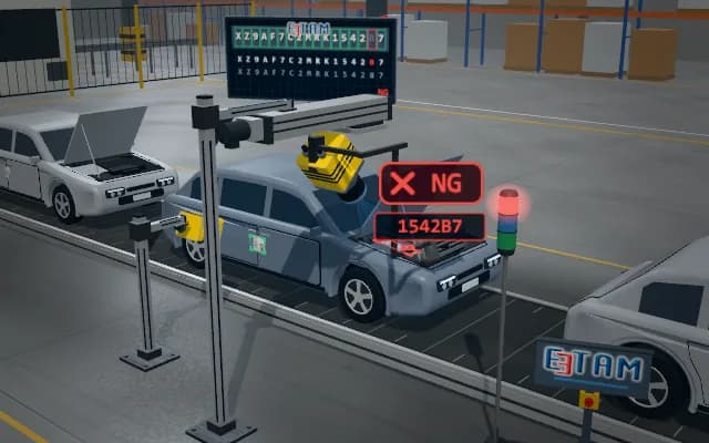
The welded subframe part sits in an inline fixture. A robot carries a 3D measuring head to the hole and mounting-face features; diameter, position and flatness are evaluated against the nominal model. Every part is measured and the result is written to statistical process control.
The value and deviation of every feature are written to the SPC database with the part number; an out-of-tolerance part is removed from the line. When a trend approaches the limit, a correction warning is sent to the welding cell.

- 01 Locate
- 02 Scan
- 03 Measure
- 04 Evaluate
- 05 Report
The part arrives in the measuring fixture and is clamped.
- Feature
- —
- Deviation
- —
- Tolerance
- —
Scenes are illustrative simulations; they are not customer references or performance guarantees.
Need
Welding heat distorts the part; holes and mounting faces shift relative to each other. The part is large, reflective and geometrically complex; a coordinate measuring machine can only check samples, and in the meantime a deviation spreads into production.
Solution approach
A structured-light 3D head on the robot captures a dense point cloud of the surface at each measuring position. The cloud is aligned to the part coordinate system through reference points on the fixture; a circle is fitted to the hole edge and a plane to the mounting face, and the results are compared with the GD&T tolerances.
Process steps
- 01
Locate
The part arrives in the measuring fixture and is clamped.
- 02
Scan
The robot moves the measuring head to the next feature and scans it.
- 03
Measure
A circle and a plane are fitted to the point cloud.
- 04
Evaluate
The deviations are compared with the tolerances.
- 05
Report
The result is written to SPC and the part is routed by the decision.
Related applications



Let us assess your application together
We test your sample in our laboratory and report on resolution, optics and lighting selection.