

Robotic nesting of forgings by pose and orientation
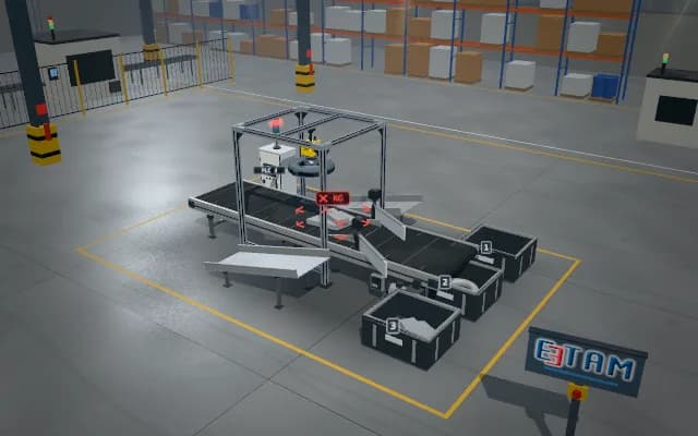
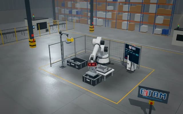
Forgings arrive on a pallet at different orientations. Visible surface and orientation are derived from laser profiles; the robot rotates its wrist during pickup, placing accepted parts into oriented fixtures and uncertain examples into a separate nest.
The 3D grip pose, orientation class and fixture address are sent to the robot. Accepted matches enter the correctly oriented nest; low-score matches remain separate from automatic assembly.

- 01 Infeed
- 02 Trigger and acquire
- 03 Analyse
- 04 Class and position
- 05 Controlled sorting
The pallet-mounted part enters the scanning position.
- Accepted class
- —
- Decision score
- —
- Target output
- —
Scenes are illustrative simulations; they are not customer references or performance guarantees.
Need
Similar silhouettes of forgings can represent opposite orientations. Partial occlusion and surface variation affect grip pose; a 2D centre point alone is insufficient for correctly oriented nesting.
Solution approach
A laser profiler scans across the surface and ordered profiles build a point cloud. Geometric matching and visual class validate the grip pose. Robot position is transferred to calibrated coordinates; the part is rotated to the target orientation before placement.
Process steps
- 01
Infeed
The pallet-mounted part enters the scanning position.
- 02
Trigger and acquire
Laser profiles are acquired across the part.
- 03
Analyse
The point cloud and orientation features are matched.
- 04
Class and position
Grip pose and target fixture orientation are assigned.
- 05
Controlled sorting
The robot lifts, rotates and lowers the part into its nest.
Related applications




Let us assess your application together
We test your sample in our laboratory and report on resolution, optics and lighting selection.