

Grip-pose and reach verification from a 3D point cloud
The 3D candidate, reach checks and simulated transfer remain traceable. Successful pose detection alone is not motion permission; colliding or unreachable paths stay under review. Vision, robot and PLC states are an illustrative solution concept.
The 3D candidate, reach checks and simulated transfer remain traceable. Successful pose detection alone is not motion permission; colliding or unreachable paths stay under review.

- 01 Image and reference
- 02 Pose and evaluation
- 03 Grip and lift
- 04 Controlled transfer
- 05 Final check and record
Scan the flange surface in the bin and mark one candidate 3D pose.
- Illustrative pose offset
- —
- Illustrative grip confirmation
- —
- Completed transfers
- —
Scenes are illustrative simulations; they are not customer references or performance guarantees.
Need
A visible flange surface can yield a pose candidate while its gripper approach remains unreachable. Point cloud, grip point, robot reach and bin neighbours require separate checks rather than one undifferentiated suitability score.
Solution approach
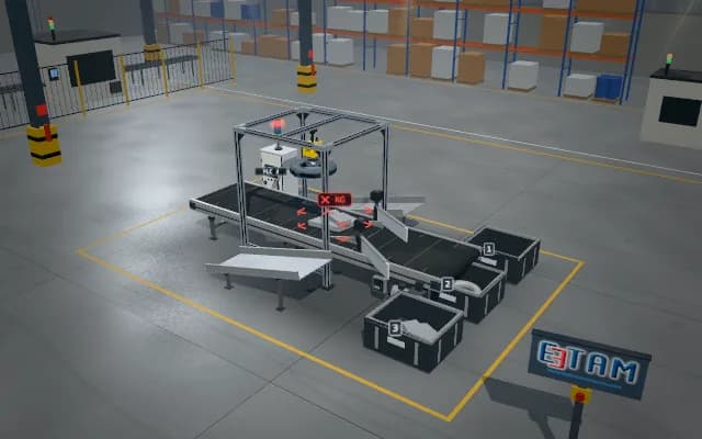
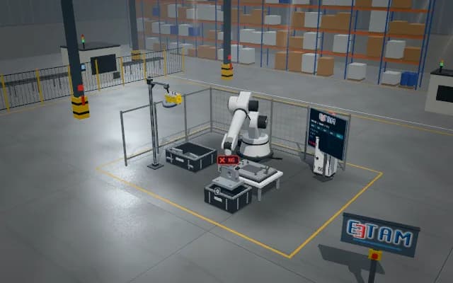
Represent flange pose and grip point from the 3D surface. Show gripper volume, approach clearance and reach as separate states; distinguish path validity from pose detection. Grip a usable candidate, lift clear of the bin, place into the destination nest and verify final seating.
Process steps
- 01
Image and reference
Scan the flange surface in the bin and mark one candidate 3D pose.
- 02
Pose and evaluation
Show grip point, reach and approach clearance as separate simulated checks.
- 03
Grip and lift
Approach the validated candidate; grip and lift the flange clear of bin neighbours.
- 04
Controlled transfer
Carry the flange attached to the gripper towards the destination nest.
- 05
Final check and record
Lower and release the flange; link final placement to its pose candidate.
Related applications



Let us assess your application together
We test your sample in our laboratory and report on resolution, optics and lighting selection.