

Non-contact 3D measurement of plastic parts
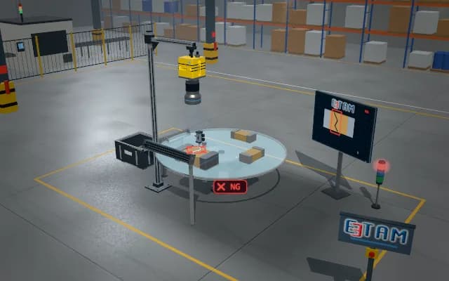
The moulded part sits in the nest and a laser profile sensor on a linear axis scans it end to end. The resulting point cloud is registered to the nominal model: key dimensions are extracted and warpage is shown as a deviation map.
Length, width and corner deviation appear on the display and HUD; the out-of-tolerance corner is marked in the map and on the part, and the tower signals the result.

- 01 Laser scan
- 02 Compare
- 03 Dimensions
- 04 Decide
The profile sensor passes over the part and the laser line samples the surface section by section.
- Length
- —
- Width
- —
- Warpage
- —
Scenes are illustrative simulations; they are not customer references or performance guarantees.
Need
Ribs and screw bosses interrupt the profile line on dark plastic; the measured cloud must be registered to the nominal model to separate seating differences from actual corner warpage.
Solution approach
The bridge axis moves the laser line across the part in a fixed direction and sections form a point cloud. Reference edges register it to the nominal model before deviation, length and width are computed; the operator display shows the scanned area and local corner deviation.
Process steps
- 01
Laser scan
The profile sensor passes over the part and the laser line samples the surface section by section.
- 02
Compare
The point cloud is registered to the nominal model and each point is coloured by its deviation.
- 03
Dimensions
Length and width are computed from the reference edges in the cloud.
- 04
Decide
Dimensions and warpage are compared with the tolerances.
Related applications




Let us assess your application together
We test your sample in our laboratory and report on resolution, optics and lighting selection.