

Weld-bead cross-sectional area and undercut measurement
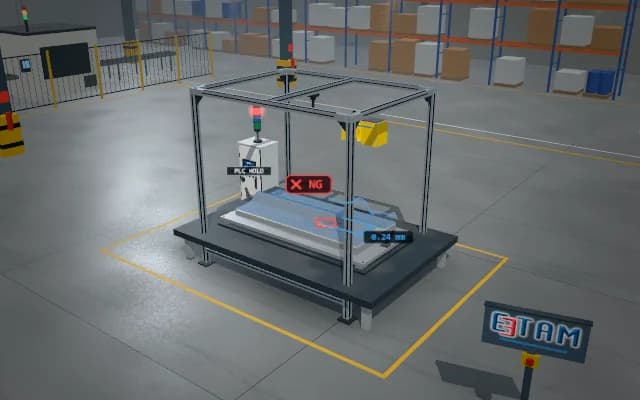
A seam joining two sheets is measured by controlled laser profiling. After the base-material plane is separated, cross-sectional area and undercut depth are calculated and findings are shown on a section plot.
Section area, undercut depth and worst location along the seam enter the measurement record. The PLC issues a part-hold or review request; surface profiling does not establish internal penetration or weld strength.
- 01 Locate
- 02 Reference and trigger
- 03 Sample
- 04 Geometric analysis
- 05 Tolerance and PLC
The weld coupon is fixed in its fixture.
- Weld cross-sectional area
- —
- Undercut depth
- —
- Sampling progress
- —
Scenes are illustrative simulations; they are not customer references or performance guarantees.
Need
A weld bead is bright and uneven; sheet tilt can resemble bead height. Cross-sectional area and undercut must reference the base material and must not be presented as an internal weld-defect result.
Solution approach
The profiler advances along the seam while acquiring transverse laser sections. Successive profiles form a point cloud and both base-material surfaces establish a reference plane. Bead area above the plane and local edge depression depth are calculated separately.
Process steps
- 01
Locate
The weld coupon is fixed in its fixture.
- 02
Reference and trigger
Base-material plane reference and trigger are verified.
- 03
Sample
Transverse laser sections accumulate along the seam.
- 04
Geometric analysis
Section area and edge-depression depth are extracted.
- 05
Tolerance and PLC
The surface-geometry limit determines the PLC review request.
Related applications



Let us assess your application together
We test your sample in our laboratory and report on resolution, optics and lighting selection.