

3D profile-based robot path correction for weld seams
Illustrative path offset, tool alignment and completed path appear together. Insufficient profile visibility requests path review; no weld arc, thermal outcome or quality certification is produced. Vision, robot and PLC states are an illustrative solution concept.
Illustrative path offset, tool alignment and completed path appear together. Insufficient profile visibility requests path review; no weld arc, thermal outcome or quality certification is produced.

- 01 Profile and reference
- 02 Path offset
- 03 Tool alignment
- 04 Path following
- 05 Geometry and record
Keep the workpiece fixed; show the seam-profile reference and start.
- Path offset
- —
- Tool alignment
- —
- Completed paths
- —
Scenes are illustrative simulations; they are not customer references or performance guarantees.
Need
A sheet joint can shift from the nominal robot path or exhibit a changing profile gap. Track path reference, tool alignment and visible seam geometry; detecting geometry does not establish weld quality.
Solution approach
Image the fixed workpiece profile reference and associate the nominal path with an illustrative lateral offset. Align the wrist profile head and tool at the seam start, then follow the path without moving the workpiece. Show end geometry and the PLC record; the welding process is not modeled.
Process steps
- 01
Profile and reference
Keep the workpiece fixed; show the seam-profile reference and start.
- 02
Path offset
Associate nominal path with the illustrative offset and prepare tool approach.
- 03
Tool alignment
Align the profile head and tool at the seam start; no workpiece gripping occurs.
- 04
Path following
Follow the seam on the fixed workpiece; animate profile and path-correction concepts.
- 05
Geometry and record
Show geometry and PLC results at path completion; the workpiece remains in its fixture.
Related applications
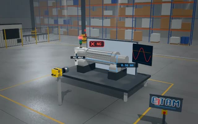
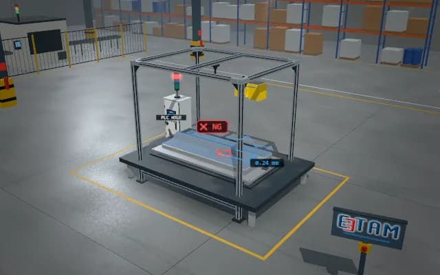

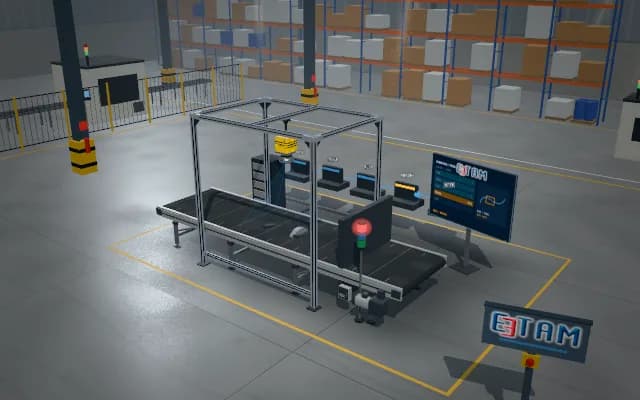


Let us assess your application together
We test your sample in our laboratory and report on resolution, optics and lighting selection.