

Crack and grinding-mark inspection on bearing rings
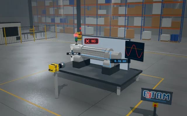
The bearing ring rotates on rollers; directional lighting and a side line-scan camera form an unwrapped image of the polished side face. A region containing a fine crack is marked and the ring is pushed into the reject bin.
Crack location and the unwrapped image are added to the part result; the defective ring is pushed into the reject bin.

- 01 Nest
- 02 Rotate
- 03 Scan
- 04 Analyse
- 05 Reject
The ring enters the roller nest.
- Scanned circumference
- —
- Crack length
- —
Scenes are illustrative simulations; they are not customer references or performance guarantees.
Need
Regular grinding marks and glare on a ground ring can resemble a fine crack. Rotation is synchronized with line images to sample the complete surface at the same illumination angle.
Solution approach
Rollers rotate the ring. A side line-scan camera samples a narrow surface strip under oblique bar lighting; directional light increases local crack contrast. Successive strips form a circumferential unwrapped image and discontinuities distinct from grinding marks are highlighted.
Process steps
- 01
Nest
The ring enters the roller nest.
- 02
Rotate
The rollers turn and directional light switches on.
- 03
Scan
Line images accumulate into an unwrapped surface image.
- 04
Analyse
Local discontinuities are compared with the grinding texture.
- 05
Reject
The cracked ring is pushed into the reject bin.
Related applications


Let us assess your application together
We test your sample in our laboratory and report on resolution, optics and lighting selection.