

3D profile inspection of robotic weld seams
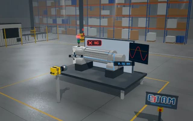
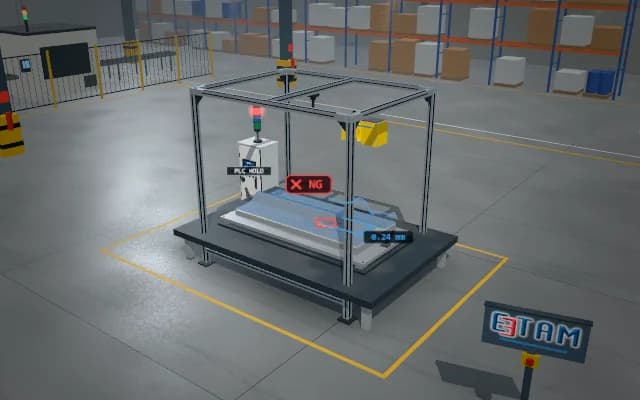
While a welded bracket sits in its fixture, a laser profiler on the robot flange travels along the seam. Cross-section width and height are compared with a reference template; the section containing undercut is marked red.
Cross-sections along the seam and the NG region position are linked to the measurement record; the profile display and stack light show the bracket rework decision.

- 01 Fixture
- 02 Laser
- 03 Scan
- 04 Profile
- 05 Decide
The bracket sits in the fixture and the robot moves to the start.
- Seam width
- —
- Seam height
- —
- Undercut depth
- —
Scenes are illustrative simulations; they are not customer references or performance guarantees.
Need
Glare on the weld and the bracket angle can hide undercut in a flat image. Measuring cross-section height along the seam reveals local material loss.
Solution approach
The robot carries the sensor along the seam with the laser line perpendicular to it. Each triangulated section is aligned to the base faces; seam width and height are compared with the reference band. A low profile at one edge is marked as undercut.
Process steps
- 01
Fixture
The bracket sits in the fixture and the robot moves to the start.
- 02
Laser
The laser line is placed perpendicular to the seam.
- 03
Scan
The robot accumulates cross-sections along the seam.
- 04
Profile
Sections are compared with the reference tolerance band.
- 05
Decide
The undercut region is marked and a rework result is issued.
Related applications


Let us assess your application together
We test your sample in our laboratory and report on resolution, optics and lighting selection.