

Winding and slot inspection of electric motor stators
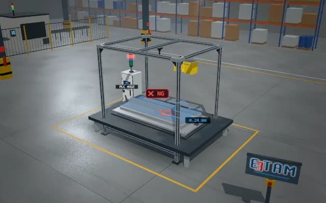
The stator pallet stops beneath a large telecentric camera; ring light illuminates the slots and winding ends. Wire positions and insulation boundaries are compared in a slot map; a stator with a protruding wire is assigned to repair.
Wire deviation by slot and the non-conforming region map are added to the stator result; an NG pallet is sent to the repair route by the routing flap.

- 01 Pallet
- 02 Acquire
- 03 Slots
- 04 Wire position
- 05 Decide
The stator pallet stops beneath the overhead camera.
- Inspected slots
- —
- Wire position deviation
- —
- Non-conforming slots
- —
Scenes are illustrative simulations; they are not customer references or performance guarantees.
Need
Bright copper wires, dark slots and thin insulation paper create different contrasts. Comparing slots against a common reference helps distinguish displaced wires.
Solution approach
The overhead telecentric camera sees all slots at a consistent scale; ring lighting illuminates winding edges around the circumference. The stator centre is located and each slot matched with a reference template. Wire position relative to the insulation boundary and protruding wires are checked.
Process steps
- 01
Pallet
The stator pallet stops beneath the overhead camera.
- 02
Acquire
An overhead slot image is acquired under ring lighting.
- 03
Slots
The centre is located and the slots matched to the template.
- 04
Wire position
Wire edges are measured relative to insulation boundaries.
- 05
Decide
A protruding wire is marked and the pallet routed to repair.
Related applications


Let us assess your application together
We test your sample in our laboratory and report on resolution, optics and lighting selection.